
Drawing Tools > The Measurement Tool
 
|
The Measurement Tool
The measurement tool is used to measure features in an image.
Before the measurement tool can be used to produce valid measurements for a particular image, you must ensure that the image is calibrated. For many types of instruments, the magnification calibration information is automatically transferred along with the image. If you are using another type of instrument, the image must be manually calibrated. Whether or not an image is calibrated is shown by a "Calibrated" indicator in the status bar at the bottom of the image. If manual calibration is required, there are two ways to do this:
- The first calibration method is to use the Micron Marker Button. To use this technique, press the micron marker button and enter the image's magnification. You can prevent the actual drawing of the micron marker by ensuring that the Display Micron Marker option is not selected. Make sure that the Calibrate Measurement Functions option is selected. PCI/CFR will use your microscope's calibration information to automatically determine the width of the image based upon the magnification that you entered.
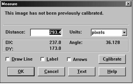
- The second calibration technique is to use the measurement tool itself. Do this by measuring the length of a known feature (such as the micron bar from the microscope) as described in the next paragraph. When the measurement dialog comes up, enter the actual length of the feature into the Distance edit control. Enter the measurement units into the Units edit control or select the units from the list of units by pressing the arrow button next to the Units edit control. Subsequent measurements will automatically be based upon this calibration. You can change the calibration in subsequent measurements by checking the override checkbox that will appear on the dialog the next time you make a measurement. You can elect not to draw the line or label the measurement by ensuring that the Draw Line and Label check boxes are not selected or by simply pressing the Calibrate button. The Calibrate button sets the measurement calibration without drawing a line or label, regardless of the checkbox settings.

To make a measurement, move the mouse to one end of the line you want to measure and press the left mouse button. While still holding down the button, drag the mouse to the other end of the line and release the button. You can constrain the mouse movements to the horizontal or vertical directions by holding down the Shift key while you are dragging the mouse. Once you release the button, the measurement dialog will appear. The measurement dialog will display the length of the line that you just selected. If you change the measurement units, a new distance value will be automatically computed using the appropriate conversion factor. By selecting the Draw Line and Label check boxes, you can show the measurement on the image. Pressing the text button allows you to edit the label text and to change the font used for the label (see The Text Tool for more information). You can also adjust the calibration at this point as described above.
Based on the calibration, PCI/CFR will attempt to make a reasonable estimate of the number of significant figures to show. If you want to adjust the computed figure, you can use the Text button to modify the number that will be displayed on the image.
Like the micron marker, the measurement will be placed in the overlay as two separate objects-the line and the label. Each of these can be manipulated independently.
 
|